📘 Path Introduction
🏘️ NoesisGUI ▸ 🏠 Noesis Studio ▸ 📘 Working With Paths ▸ 📘 Path Introduction
Overview

One of the most powerful features of both the NoesisGUI Runtime, as well as Noesis Studio, is native support for vector graphics.
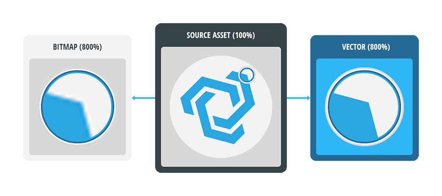
Vector graphics differ from bitmap (or 'raster') graphics in that, instead of being composed of individually-mapped pixels within a fixed-size canvas, they are created through the use of mathematical formulas. These formulas, which are generated behind-the-scenes during the vector artwork authoring and manipulation process, capture information about shapes, lines, and colors.
Because vectors are mathematically-based, they offer the unique advantage of benefitting from unlimited size scalability without suffering from any quality loss. This makes them particularly well-suited for usage within a digital user interface which could be displayed at a wide range of screen dimensions and resolutions. Their ability to retain their fidelity and maintain a high level of sharpness as they scale up and down also also makes them an ideal candidate for being the subject of animations.
Another particular advantage of using vector graphics within the Noesis framework, is the ability to 'hook into' the artwork's vector data, to be able to manipulate it in a dynamic, non-destructive manner on-the-fly, such as being able to recolor assets to match a theme, or to completely change the shape of a piece of vector artwork without requiring multiple assets.
Due to how vectors are constructed, they are almost always the best choice for relatively simple, and relatively flat graphics (such as iconography or shapes), whilst a bitmap graphic may be better-suited for higher-detail, more complex imagery (such as photographs or complex illustrations).
Anatomy of a Path
Path Geometry
Within the framework, the geometry of a vector shape is referred to as a Path containing the mathematical data that makes up the visible shapes, in what is referred to as its PathGeometry.
A Path's PathGeometry is composed of one, or many PathFigures, which themselves are made up of Path Points, and the Path Segments that join the Points together
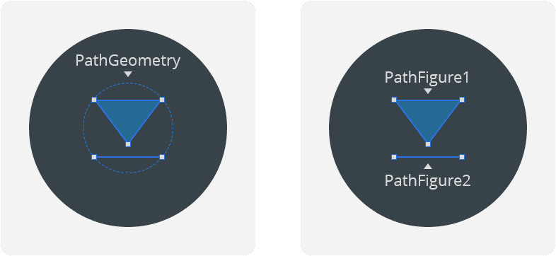
The individual PathFigures that make up a particular PathGeometry can be composed of Segments (such as a single line), simple closed shapes (such as a basic square or an ellipse), or complex 'composite' (or 'compound') shapes (such as as a 'donut' shape composed of one ellipse within another).
Additionally, any 'enclosed' Path can be combined with another to create various new shapes from the way they intersect together by 📘 Compounding Paths, 📘 Clipping Paths, or through 📘 Boolean Operations.
Path Segments and Path Points
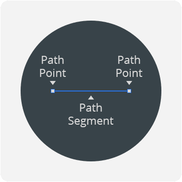
At a basic level, each Segment of a PathFigure is composed of two Path Points (a Start Point, and End Point), and a line joining the two together.
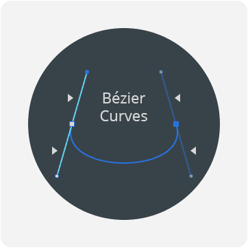
Segments can be manipulated even further through the use of Bézier curves, which allow the Segment between the two Path Points to be curved through a pair of handles called Point Handles, which are bound to each Path Point.