📘 Path Properties
🏘️ NoesisGUI ▸ 🏠 Noesis Studio ▸ 📘 Working With Paths ▸ 📘 Path Properties
Overview
Paths come with a number of Properties that can be both bound to backend systems, or edited by hand to either fine-tune the presentation of a vector graphic, or to be dynamically modified between Styles, Visual States, or within animations.
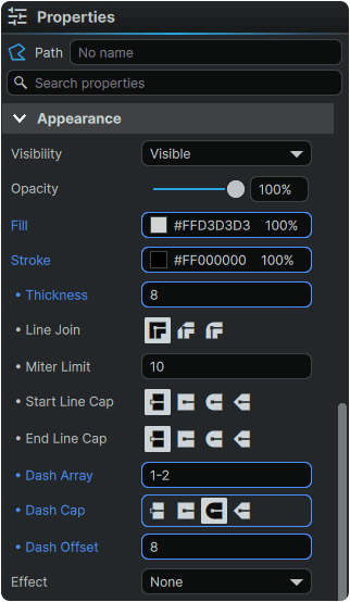
Path Appearance Properties
The Path Properties govern the presentation of the entire vector Path as a whole, including all compound or separate shapes and segments contained within.
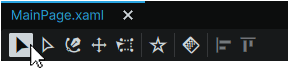
To select a Path and access its Properties, the Selection Tool can be equipped from the 📘 Toolbox, or by pressing V. With the Selection Tool equipped, a Path can then be clicked either from the 📘 Stage or from the 📘 Navigator Panel to expose its Properties within the 📘 Properties Panel.
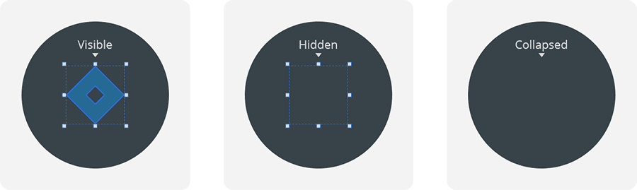
Path Visibility
Sets the visibility of the entire Path between:
- Visible: The Path is visible, and occupies space in the layout.
- Hidden: The Path is not visible, but occupies the space in the layout it would occupy if it were Visible.
- Collapsed: The Path is not visible, and does not occupy any space in the layout.
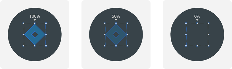
Path Opacity
Sets the transparency of the entire Path between 100% (fully opaque) and 0% (fully transparent).
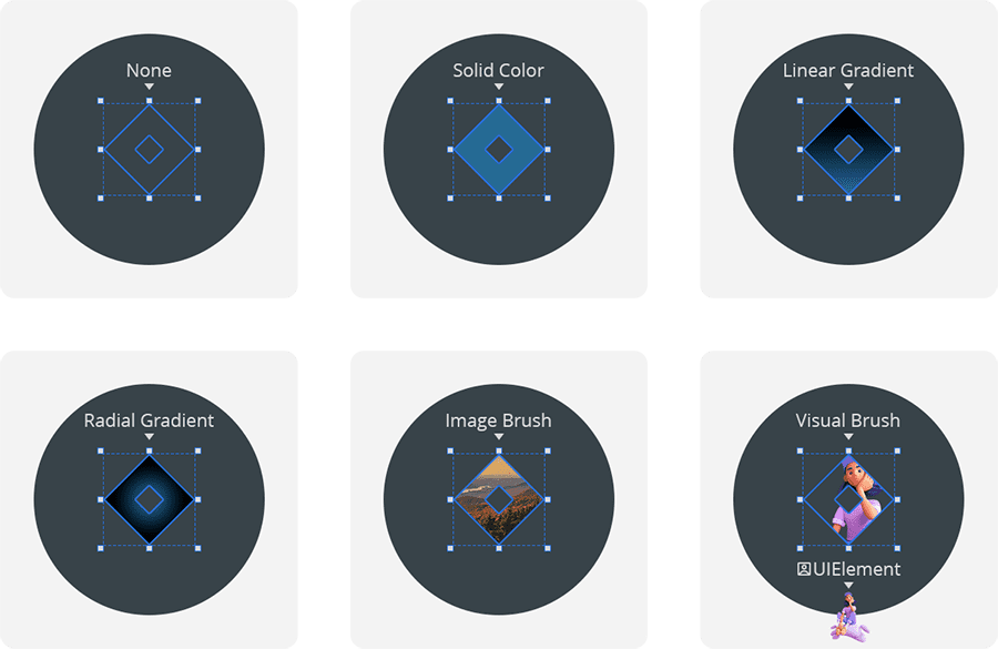
Path Fill
Sets the interior fill of the Path between:
- None: No fill.
- Solid color brush: Fills the Path with single value containing both a color and opacity value.
- Linear gradient brush: Fills the Path with multiple values in series, each containing a color and opacity value, with the series laid out in a seamless linear line in a direction.
- Radial gradient brush: Fills the Path with multiple values in series, each containing a color and opacity value, with the series emanating from the center of the Path in a direction.
- Image brush: Fills the Path with a bitmap image.
- Visual brush: Fills the Path with the visual of a targeted Element located within the project.
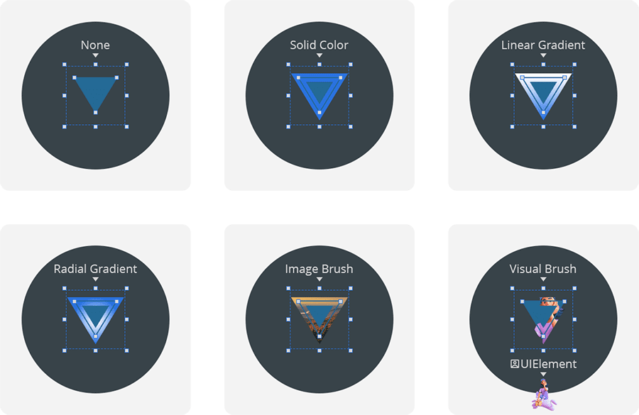
Path Stroke
Sets the exterior outline of the Path between:
- None: No fill.
- Solid color brush: Fills the Path with single value containing both a color and opacity value.
- Linear gradient brush: Fills the Path with multiple values in series, each containing a color and opacity value, with the series laid out in a seamless linear line in a direction.
- Radial gradient brush: Fills the Path with multiple values in series, each containing a color and opacity value, with the series emanating from the center of the Path in a direction.
- Image brush: Fills the Path with a bitmap image.
- Visual brush: Fills the Path with the visual of a targeted element located within the project.
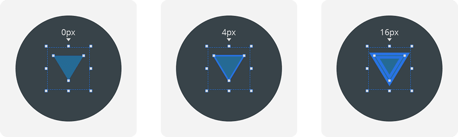
Stroke Thickness
Sets the size of the Path's Stroke, measured in pixels, between 0 px (no stroke) and ∞ px (infinite-thickness).
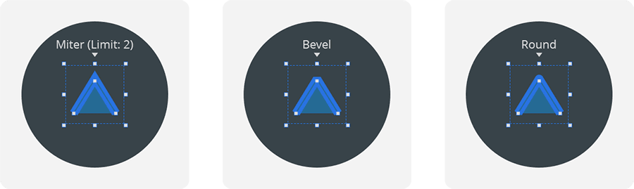
Stroke Line Join
Sets the presentation of the Stroke's anchor point tips that are connected to two segments, between:
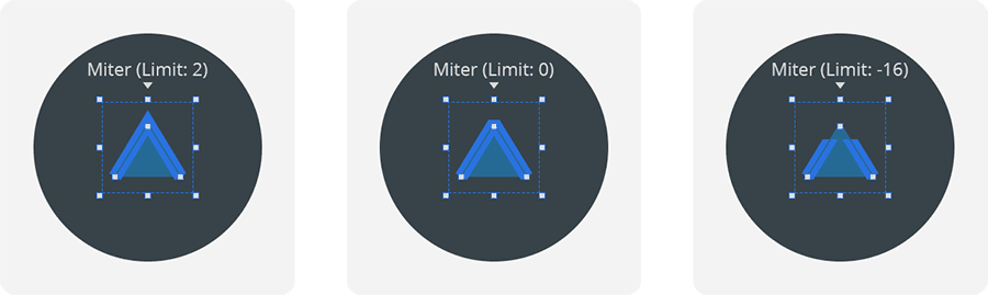
- Miter: Clips the corner at an angle equal to the average angle of both connecting segments. With the Miter Limit property, can be set to clip at a specific distance from the anchor point.
- Bevel: Clips the corner at an angle equal to the average angle of both connecting segments. Clips at the anchor point.
- Round: Rounds the corner of a Stroke to a diameter equal to the Thickness of the Stroke.
Stroke Miter Limit
When the 'Miter' Line Join type is selected, sets the distance in pixels from - ∞ px (negative infinite) to ∞ px (positive infinite) away from the anchor point, at which the Stroke's corner is clipped.
Stroke Start Line Cap / Stroke End Line Cap
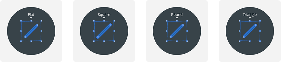
For 'open' Paths, sets the presentation of the Stroke's first and last Path Point tips between:
- Flat: Clips the anchor point tip at an angle equal to the connecting segment's angle, at the anchor point.
- Square: Projects a square tip at an angle equal to the connecting segment's angle, at a distance equal to half of the Thickness of the Stroke.
- Round: Projects a circular tip at an angle equal to the connecting segment's angle, at a distance and radius equal to half of the Thickness of the Stroke.
- Triangle: Projects a pointed tip at an angle equal to the connecting segment's angle, at a distance equal to half of the Thickness of the Stroke.
Stroke Dash Array
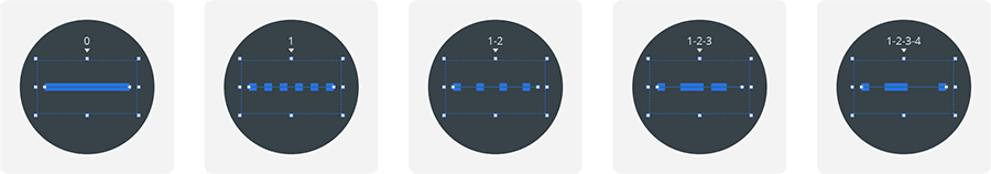
Sets whether a Stroke is composed of Dash-Gap pairings that are repeated across the length of the Stroke to make up a dashed line. The Dash Array can be composed in any of the following formats:
- '0' will render a solid, non-dashed Stroke. Leaving the field empty will produce the same result.
- '1' will render a repeating dashed Stroke with a Dash equal to the Thickness of the Stroke, and a Gap equal to the Thickness of the Stroke.
- '1 2' or '1,2' or '1-2' will render a dashed Stroke with a Dash equal to the Thickness of the Path, and a Gap equal to double the Thickness of the Stroke.
- '1 2 3' or '1,2,3' or '1-2-3' will render a dashed Stroke with a first Dash equal to the Thickness of the Path, a first Gap equal to double the Thickness of the Path, and a second Dash equal to triple the Thickness of the Path. In a series of uneven numbers ending with a Dash, the first number in the sequence then becomes the Gap, as the numbers are cycled through as a repeat pattern.
- '1 2 3 4' or '1,2,3,4' or '1-2-3-4' will render a dashed Stroke with a first Dash equal to the Thickness of the Path, a first Gap equal to double the Thickness of the Path, a second Dash equal to triple the Thickness of the Path, and a second Gap equal to quadruple the Thickness of the Path.
The Dash Array value can take an infinite amount of Dash-Gap values, and can extend beyond the examples above, allowing for total customization of the Dashes and Gaps across the entirety of a given path.
Stroke Dash Cap
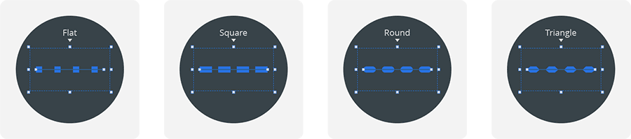
Sets the presentation of the tips of the Dashes within a Dash Array between:
- Flat: The length of the Dashes match the value set in the Dash Array.
- Square: Projects a square tip to the length of the Dash, at a distance on each side equal to the Thickness of the Stroke.
- Round: Projects a circular tip to the length of the Dash, at a distance and diameter on each side equal to half of the Thickness of the Stroke.
- Triangle: Projects a pointed tip to the length of the Dash, at a distance on each side equal to half of the Thickness of the Stroke.
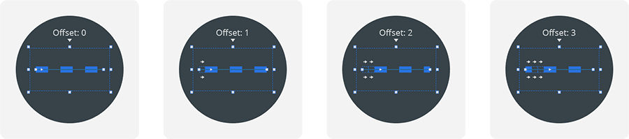
Stroke Dash Offset
Shifts the beginning of the Dash Array along the Path by a factor of the Thickness of the Stroke.
For example:
- On a Stroke with a Thickness of '2px', setting a Dash Offset of '1' will shift the beginning of the Dash Array over by 2px.
- On a Stroke with a Thickness of '8px', setting a Dash Offset of '2' will shift the beginning of the Dash Array over by 16px.
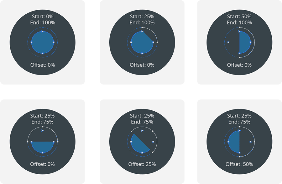
Path Trim Start / Path Trim End / Path Trim Offset
Sets a Path to be dynamically 'masked' along the direction of the Path itself, starting from a single 'start' anchor point, and rotating clockwise. Trim values are expressed as a percentage of the Path's total length between 0 (start of Path) and 1 (end of Path).
The 'Trim Start' and 'Trim End' points can be used to manually specify an artificial 'start' (and 'end') point beginning (or ending) at any percentage of distance along the total Path length.
The 'Offset' value can be used to manually 'shift' the values of the Trim Start and Trim End by a percentage of the total Path length.
The 'start' point of a Path is defined as either:
- The first anchor point placed when drawing a new Path.
- The top-left most anchor point of a prefabricated Shape. If two points are equal distance to the top-left corner, the 'start' point is awarded to the top-most point within the Path.
or
- A manually-designated 'start' point, as set in the Path Point's Properties.
Path Point Properties
The Path Point Properties govern the attributes of a single Path Point selected within a PathFigure.
Path Point Selection
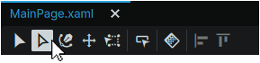
To select a Path Point, select the Path Selection tool either by clicking on it from the Toolbox, or with the A shortcut.
Set as Starting Point
Assigns the selected Path Point as the 'starting point' for the PathFigure in a Path. This impacts where the Path's 'Trim Start' will begin along the Path and where a Path's Dash Array will begin from.
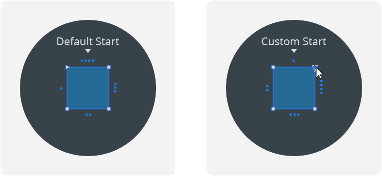
Note
Note that this option is only available for enclosed Paths, and does not apply to 'open' Paths.
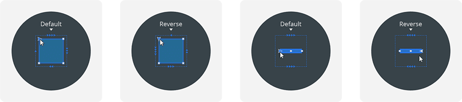
Reverse Direction
Toggles the 'direction' of a Path between clockwise and counter-clockwise, or vice-versa, and determines the direction in which a 'Path Trim' circulates around an individual PathFigure within a Path.
On an 'open' Path, reversing the direction changes the 'starting' Path Point from one end, to the other.
Stage Coordinates / Position
Sets the horizontal (X) and vertical (Y) position of an anchor point relative to the 0,0 coordinates (upper-left-hand corner) of the entire Stage, or if unchecked, relative to the 0,0 coordinates of the Path.
When the 'Stage Coordinates' property is unchecked, in the case of hand-drawn Paths, the coordinate position value is relative to the first anchor point placed (Coordinate: 0,0).
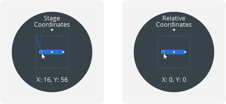
In the case of a Primitive Shape converted to a Path, the coordinate position corresponds to the top-left corner of the Path's bounding box (Coordinate: 0,0) at the moment of conversion from a Shape to a Path.
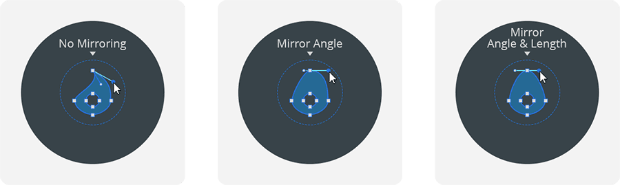
Curve Handles Mirroring
When an anchor point features a curve, sets the relationship between both handles of a Path Point between:
- No mirroring: Each anchor point handle is able to move independently, both in angle and length.
- Mirror angle: Each anchor point handle can be of any length, but both handles will angle in tandem to symmetrically reflect eachother.
- Mirror angle and length: Both anchor points are symmetrically mirrored both in angle and in their distance from their connecting anchor point.
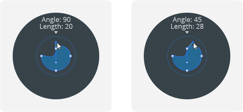
Curve Handle 1 / Curve Handle 2
Sets the angle of each handle, as well as their distance away from their respective anchor point.
Working With Paths
- 📘 Path Introduction
- 📘 Path Import Features
- 📘 Path Creation and Manipulation
- 📘 Path Management
- 📘 Path Properties
- 📘 Path Animation
Table of Contents